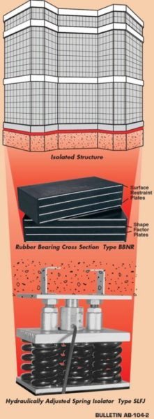
Noise and vibration isolators are used to prevent the downward transmission of vibration from a machine to a structure, the upward transfer from the structure to a sensitive machine or to isolate a complete building from ground vibration. Ground vibration may be generated by above ground or under ground passenger or freight trains, or heavy motorized vehicles, such as trucks or military equipment. The source may be industrial hammers, power plants or industrial machines, close enough to cause a problem.
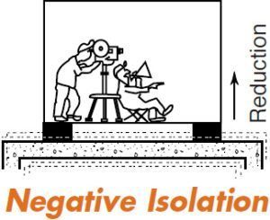
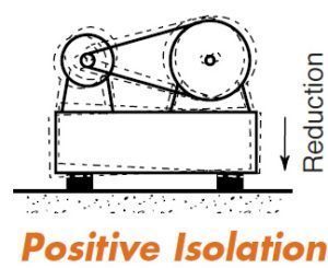
When the isolators are installed to prevent the downward flow of vibration from a source to the ground or structure, it is termed “positive isolation”. When the reverse is true and the isolators prevent the upward passage of vibration, it is “negative isolation”.
Steel springs are more effective, but Neoprene and Natural Rubber pads are also used to reduce vibration to entire structures or structural components such as individual floors or a theater within a building, to levels that are unnoticeable or totally acceptable.
The simplified theoretical isolation efficiency equation is:

Since the disturbing frequency can be measured or from a known source, the variable is the pad frequency or resonance. This frequency is a function of deflection, the shape of the load – deflection curve and dynamic stiffness.
Helical steel springs have straight line load deflection curves and the dynamic stiffness at fd is the same as the static stiffness (stiffness when loaded slowly).
If a steel spring were deflected 0.3” (7.6mm), the frequency would be:

Rubber materials do not test that way because they have “Dynamic Stiffness”. When the pad is vibrated, it resists the rapid motion, so the spring rate in motion (dynamic) is higher than the static stiffness indicated on a load versus deflection curve. Dynamic Stiffness is expressed as the ratio:
Dynamic Spring Rate/Static Spring Rate
The static deflection must be reduced by the Dynamic Stiffness ratio before it can be entered in the frequency equation. Therefore, larger static deflections are needed when using rubber isolators as compared to springs, to obtain the same reduction in vibration transmission.
In broad terms, dynamic stiffness is controlled by:
The Polymer: Natural Rubber has the lowest dynamic stiffness of all the common materials. The synthetic material, Neoprene, comes next. There is virtually no data on other polymers, because they are not used for this purpose.
Filler Ratios: Rubber materials are similar to concrete in the sense that by varying the formula you can produce different properties. When mixing concrete, the reinforcing materials are sand and gravel. In mixing rubber, high quality compounds are reinforced with carbon blacks. The inexpensive compounds with poor physical properties may use cheap fillers like clay, talc and sometimes coal particles. In order to keep dynamic stiffness low, the black fillers are kept to a weight ratio that is never over half that of the Natural Rubber.
Durometer: Harder materials with larger proportion of black fillers will tend to have higher dynamic stiffnesses.
Most acousticians will specify a maximum dynamic stiffness of 1.4 or lower. We are pleased to say that within our company, we have developed compounds as hard as 60 durometer with a dynamic stiffness that is still in the 1.3 range. In working with our company, bearings can be designed at lower cost by using 60 durometer rubber as compared to competitors that might be limited to 50 durometer or softer materials.
If a rubber pad deflected 0.3” (7.6mm) and the dynamic stiffness was 1.3, the effective deflection would be 0.3” divided by 1.3 or 0.23” (5.9mm). Solving the Frequency equation shows a frequency of 6.5Hz. A poorer compound with a dynamic stiffness of 1.7 would reduce the effective deflection to 0.180” (4.6mm) with a corresponding higher frequency.
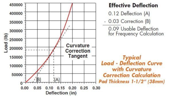
Load-Deflection Curve Shape: A second correction depends on the shape of the rubber load deflection curve. This curve is not straight line and the measured deflection must be reduced by the effect of the increased spring rate at the design loading.
Creep is additional deflection or drift over time. It is not a percentage of the pad’s thickness. Creep is a percentage of the initial deflection and a function of the rubber compound. A working number of 30% creep is reasonable. Were the initial deflection 0.3” (7.6mm), within 100 days the pad would creep 0.30 (0.3) or 0.09” (2.3mm) and for all practical purposes remain at a total deflection of 0.39” (9.9mm). This additional deflection does not reduce the frequency.
When an isolation frequency of 5.5 Hz or higher will solve the problem, rubber isolation pads are more economical than steel springs.
Rubber noise and vibration pads are used in compression at a strain of (deflection) up to 10% of the rubber thickness when supporting structures. Once the desired frequency and dynamic stiffness is known, it is a simple calculation to work back to the deflection. The deflection divided by the strain determines the thickness of the working rubber in the bearing.
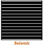
Seismic Isolation is accomplished by tall bearings with extremely low horizontal or shear frequencies. Vertical deflection is kept to a minimum as most earthquakes have high horizontal forces, and structures are more prone to horizontal resonance and failure.
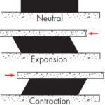
Bridge and overpass bearings work in shear to accommodate expansion and contraction. Frequency is not important and plays little or no role in the design. The rubber pad must have a minimum thickness of twice the anticipated horizontal motion. Movements are dependent on the temperature extremes and the spacing between pads.
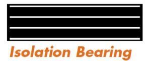
This bulletin is primarily dedicated to building or structural isolation. The nouns “pads” and “bearings” are interchangeable.
Rubber is an engineering material and design is based on both chemical and physical properties. Neoprene and Natural Rubber formulations fill both requirements. Neoprene has the advantage of better aging documentation and chemical resistance. Natural rubber is considerably less expensive and lower in dynamic stiffness. Natural Rubber aging documentation is not as formal, but with modern anti-oxidant and anti-ozonant additives, aging is no longer of major concern.
Load carrying capacity is based on:
- Hardness
- Area
- Shape Factor
- Allowable Strain
- Allowable Stress
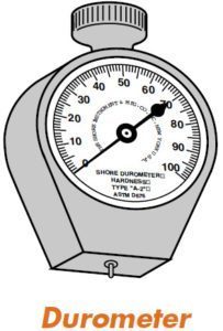
Durometer is the term for hardness as indicated by a Durometer number. The normal range for isolation is 40 to 60±5 as limited by dynamic stiffness. It is measured by a clock like instrument called a Durometer that has a spring loaded pin in the flat surface on the bottom. Penetration shows as a direct reading by a single hand that points to the hardness number. The harder the rubber, the higher the durometer and the greater the load carrying capacity.
Compression Area is the fully covered pad area at 90° to the supported load. In flat pads the shear area is identical. Shear offers horizontal resistance to wind and accidental impact from a derailed train or a large vehicle. Shear stiffness and spring back restores centering and contributes to stability.
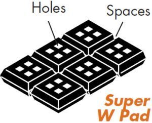
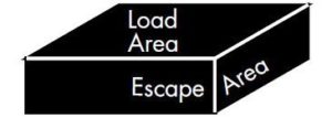
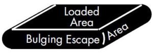
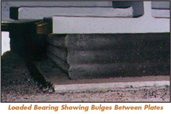
Shape Factor: Rubber is similar to a fluid and volumetrically incompressible. When the flat surface is loaded and the rubber squeezed, the rubber bulges. The bulge volume is equal to the pad deflection multiplied by the loaded area. Shape Factor is defined as the loaded area divided by the bulge or escape area. While this is usually perimeter area only, holes or cutouts can be introduced to allow for inward bulging as well. Typically, the holes or ribs in standard isolation pads, such as the “Super W”, are there to reduce shape factor.
The Shape Factor for a 12” x 12” x 1” thick pad (300mm x 300mm x 25mm) would be:

If the pad were 2” (50mm) thick, the SF would drop to 1.5 or should it be 0.75” (20mm) , it would increase to 4.
The higher the SF the greater the capacity, as it is more difficult for the rubber to bulge.
Allowable Strain is the percentage reduction of the overall thickness. A 1” (25mm) thick pad compressed 0.10” (2.5mm) has a strain of 0.10/1.00 (2.5/25) or 10% . Strain should be kept very low when there are large variations in loadings and large shear displacements such as under bridges or trestles as this type of cycling leads to fatigue. Most engineering references consider strain more critical than stress.
Highway codes such as the British BS 6177 and the American AASHTO may limit pads to as little as 6% strain. Building isolation is more passive, so
strain can be somewhat higher and subject to the designer’s experience.
We have overloaded high quality pads in our laboratory to 60% strain (6-8 times rated load) and held them for a week. They recovered 80% to 90% of the original thickness immediately and 100% in a day. The recommended strain limit had been 15% for many, many years. We do not know if the more conservative numbers are based on negative experience or arbitrarily increasing safety factors.
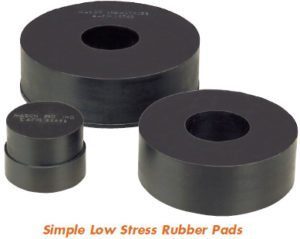
Allowable Stress is the loading per unit area. Maximum published compressive stress values are as high as 3000psi (20,680 kPa), but more commonly 2000psi (13,790 kPa). A limit of 1500psi (10,340 kPa) in compression is recommend provided strain is in the 8-10% range. Reductions in either number increase consistent performance over time. Much lower stresses are often used to provide a practical bearing size when support areas are large and loadings low.
If a 10,000 lb (4545 kg) bearing pad were to be located under a 12 inch (300mm) beam flange or the load were applied at the top of a 12 inch (300mm) square column, we would use minimum 10”x 10” (250mm x 250mm) pads both for appearance and stability. Since there are 100 square inches, the stress drops to 100psi (689 kPa), nowhere near maximum design. Therefore, loadings may be controlled by available space, stability, common sense or aesthetics rather than maximum allowable stress.
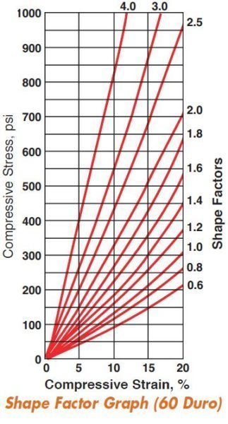
Empirical Shape Factor curves help the designer. While they are based on durometer, results can vary widely as not only do Natural Rubber and Neoprene have different characteristics, but compounds of either have different moduli in compression and shear. Shape Factor curves are a valuable design tool and used to arrive at a reasonable design. Physical testing is essential for final tuning. In our laboratory we test pads up to 750,000 lb (340,000 kg) capacity and provide computerized load deflection curves in hard copy (see photos 10 & 11, page 8). The following illustration is a typical test curve.
This is not a design manual but a general source of information as to bearing pad design. If our results differ from your experience, it is because of different references and compounds.
Earlier in our discussion we referenced a 12” x 12” (300mm x 300mm) pad in thicknesses of 2” (50mm), 1” (25mm) and 3/4” (20mm) with respective shape factors of 1.5, 3 and 4. Let us see how these pads would act by referring to the 60 durometer shape factor curves.

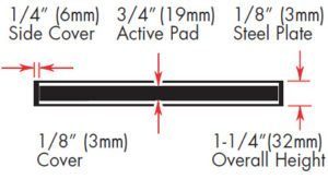
The 12” x 12” x 3/4” (300mm x 300mm x 20mm) pad at 660 psi (4550 kPa) with a shape factor of 4 does not fall into these categories. Therefore, steel plates must be bonded to each surface to prevent surface spreading. In most cases, these plates are 1/8” (3mm) thick and covered with 1/8” (3mm) bonded rubber top and bottom. There is a 1/4” (6mm) protective layer around the edges. The deflection of the 1/8” (3mm) cover is negligible as the shape factor jumps to 24, but the overall pad dimensions are now 12-1/2” x 12-1/2” x 1-1/4” (318mm x 318mm x 32mm).
Assuming the loading of 95,040 lb (43,200 kg) is correct, but the deflection of 0.06” (1.5mm) is too low to meet a frequency requirement, we would increase the number of layers.
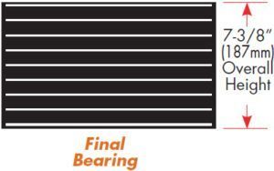
To attain 1/2” (13mm) deflection, the bearing would have eight 3/4” (19mm) active layers. The overall configuration would be nine 1/8” (3mm) bonded steel plates, 1/8” (3mm) top and bottom cover and 1/4” (6mm) pro-tection on all sides. The overall dimensions would increase to 12-1/2” x 12-1/2” x 7-3/8” (318mm x 318mm x 187mm).
There are many solutions to the problem. Shape factors are computerized so it is relatively simple to sample different solutions to arrive at the best engineering design. Designing manually from time to time is important to maintain perspective.
Our factory’s capabilities include mold manufacturing and steel work in addition to rubber mixing and molding. We have a computerized test facility. Our professional engineering department designs pads both for frequency and capacity.
All rubber products are molded under tremendous pressures of about 1,000 pounds per square inch (6895 kPa). The pressure comes from the huge hydraulic press cylinders. Heat is provided by thermostatically controlled plates above and below the molds. The ideal temperature for vulcanization depends on the thickness and type of rubber, but it is usually about 305° F (152°C). Cure time is roughly one hour per inch of thickness.
