SPRING ISOLATORS
Not all problems can be solved with rubber isolation pads. On page 2 we have indicated that the cut off point for rubber bearings is about 5.5 Hz. This would mean that the incoming frequency should not be lower than 16.5 Hz just to maintain the traditional but often unsatisfactory 90% theoretical efficiency. The efficiency equation is based on the assumption that a structure is a lumped mass or a block of concrete that has no flexibility and an infinite resonance frequency. It is also assumed that this rigid mass loads each isolator in accordance with the weight distribution as a lump mass at each location.
This assumption is false. Just as in the isolation of structural floors from machinery, the selection of a practical deflection is dependent on the sensitivity or rigidity of the structure and the various resonances of the structural elements. A lightly loaded structural floor might have a frequency as high as 7 Hz and fully loaded, 3 Hz. The frequency of the steel columns resting on the isolators might be very much higher. Concrete structures will transmit structurally induced noise over very large distances from the source with almost no attenuation.
We recently extended our own office building and some demolition was required. The construction workers were using small chipping hammers about 150 feet from my office. There was no air-borne sound transmission, but the structure-borne noise radiating from the ceiling made it seem like they were directly overhead.
In mechanical isolation work we have found that when isolating vibration at frequencies as high as 250 Hz, we have had to use air springs with a response of 3 Hz before the isolation was effective as the vibration was in the audible noise range.
Moving on to lower speed machinery at 30 Hz, we have had to use isolators with a response as low as 2 Hz (a frequency ratio of 15 to 1) before we could solve the problem.
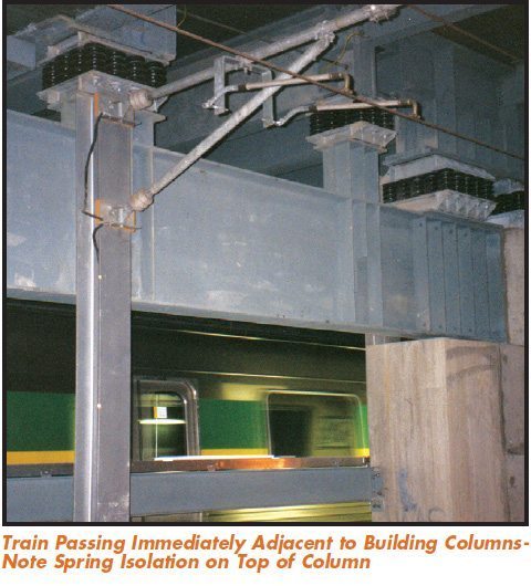
We have been involved in a number of jobs where the acoustician recognized that not only did the building not respond as one mass, but that the requirements for isolation varied in different parts of the structure. The ground vibration dissipated with distance from the source, so lesser treatment would be satisfactory further from the railroad.
In one application, the building contained office space, a cinema and a live theater. The rest was a plaza over a garage. The critical area was supported on spring mountings with a response of 3.5 Hz and the plaza area on 7 Hz rubber bearings.
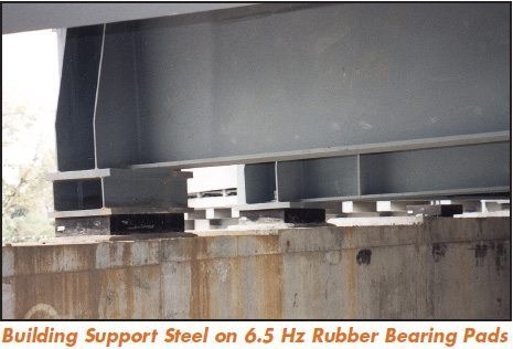
In another example, that portion of the building over the railroad tracks was supported on 2.5 Hz spring isolators. Further away spring deflections were smaller and the frequency 3.5 Hz. The extreme areas were supported on 6.5 Hz rubber bearings.
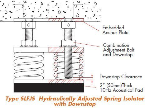
While steel spring isolators do an excellent job of stopping vibration, it is very important that high frequency noise transmission is considered too. It is our suggestion that all spring isolators have 10 Hz base isolation pads 2”(50mm) thick, manufactured to the same standards as in the earlier part of this discussion.
Spring mountings can be manufactured to any capacity. Practical designs have deflections of as much as 4”(100mm), which corresponds to a frequency of about 1.5 Hz. However, it is generally not practical to go to these numbers as the horizontal stiffness of the spring drops in proportion to the vertical and the building becomes more responsive to wind loads.
The consideration of specified deflection, and when this specified deflection occurs, is of major importance as it controls the isolation performance.
Another concern is the ratio of the dead and live loads of the structure. Live loads may be an additional 30% of dead load. If the mountings had a deflection of 3”(75mm) at dead load, it would increase to 3.9”(99mm) when fully occupied. This variation in elevation could be both a mechanical nuisance and undesirable. Therefore, we have not worked with deflections of more than 2”(50mm) at design loadings.
All structural engineers must design buildings to accommodate dead load plus the maximum conceivable live load. When specifying deflection for the isolators, whether they are rubber or spring, the acoustical engineer should specify the deflection needed to solve the acoustical problem at the lowest level of occupancy or live load when vibration and noise is a concern. If the deflection is specified at maximum load, there will be lesser deflection and lower efficiency most of the time. means the isolation will only improve at greater occupancy. However the mountings must have additional capacity to accept maximum structural loadings.
In designing spring isolators, travel can be limited beyond the most probable normal occupancy, by including limit stops. Stops parallel and bypass the springs so the load is transmitted to the lower isolation pads directly. There is an accepted loss in efficiency for those extreme structural design loadings that will probably never occur.
There are a number of issues to be addressed in deciding on isolation technique. The first is “Replaceability”.
Even though highway specifications are very demanding, when rubber bridge bearing pads are used at buttresses or pylons to accept expansion and contraction or provide vibration isolation, they always remain accessible. Hydraulic jacks can be inserted next to the pads and the pads replaced.
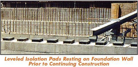
In isolating structures, this is not the general rule and pads are generally put in position and the structure proceeds. While we have no history of pads having gone bad and requiring replacement, we would suggest that if they are not made removable by using the same methods we will suggest a little further on for spring mountings, that there is provision for hydraulic jack pockets as needed. At some time, well beyond the lifetime of the architect, the structural engineer or the manufacturer, some future generation should not be left with an insoluble pad replacement problem. Lifting a structure a maximum of 0.4”(10mm) in the pad location and perhaps some immediate adjacent areas, is doable if provision is made for jacks. Since pad deflections are always relatively small, their gradual deflection as the structure progresses is of little consequence. Spring mountings are an entirely different issue.
Spring specifications generally call for no less than 0.8” (10mm) deflection, and 2”(50mm) is not unusual. As the technique becomes more common, and either performance requirements or input more severe, it is possible that deflections could move into the 4” (100mm) range. It is not practical to have a structure change elevation during construction with numbers of this magnitude. Should the loadings not be added
uniformly, the incomplete structure would suffer a change of level as well. Therefore, two methods are used to control the problem.
Precompressed Spring Assembly
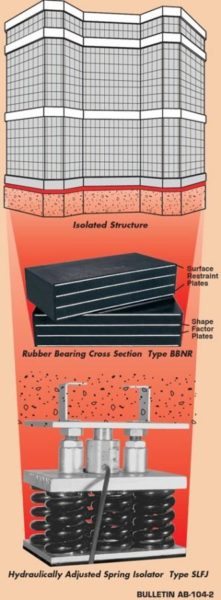
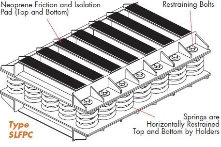
The first consists of calculating the dead load at each location. The springs are precompressed to 70% of the dead load within a structural housing similar to a clamp, as shown in the illustration. Precompression is done in a hydraulic press and each bolt tightened to hold the proper share of the load when the press is released. The mounting is a rigid support up to this 70% loading. While this method has been used for quite some time, it has its short comings.
Structural weight calculations are broad. In terms of foundation design, normal discrepancies are of no consequence. However, when the structure is dependent on springs releasing themselves, if the weight is not close to the calculation, the springs will either release too early or not at all. Hot wound spring capacity can vary plus or minus 10%. Assuming they do release exactly as planned, there is still additional travel equal to 30% of the dead load deflection plus additional live load. A 2”(50mm) spring deflection example is easier to visualize. The mountings should release at 1.4” (36mm), depending on whether the 2”(50mm) was specified at dead load or at dead load with some occupancy. They would have to travel an additional 0.6”(15mm) or more at full load. This is considerable movement as it is not just the mountings that are moving, but the whole structure.
Should the total weight be correct, but the distribution erroneous, the mountings would release and continue traveling at different times. Most important the structure is at a fixed elevation only until 70% of the assigned load is reached. Thereafter the level changes. The final elevation can not be forecast as it is weight and exact spring rate dependent.
Should there be a need to change springs, the only way to do so is to tighten the bolts so the springs cannot expand, jack up the building slightly and pull the mountings out. Alternately, you might compress the springs past the actual load by tightening the bolts. The loadings on these bolts are so high that realistically even with new clean bolts, this is all but impossible to do. Were you to do so, you would still have to establish temporary supports while removing and service the mounting.
While we do not refuse to manufacture these designs when specified by others, and do everything possible to make them user friendly, we much prefer the following approach.
Hydraulically Adjusted Spring Isolators
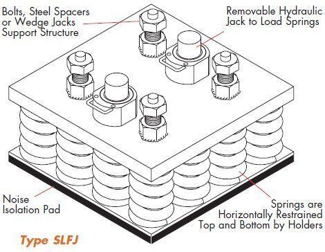
Many years ago we designed the SLRJ Mounting. They have structural steel sides with removable spacers on top that support equipment rigidly during erection. Because the equipment is held at elevation, water, electrical and other services can be completed without waiting for spring adjustment. If a mounting supports 25,000 lbs.(11364 kgs.) or more, we load the springs inside the housing with a hydraulic jack and run up the bolts on top of the spring plate to hold this adjustment. This procedure is followed all around the machine until the springs have been compressed sufficiently to retain the load and lift the equipment a few thousandths so the steel spacers can be removed. The bolts next to the jacks are advanced to hold this final adjustment and the jacks removed. The system is now spring supported without any change in elevation.

