Intro
Walls are isolated to prevent flanking around floating floors or to improve the STC between adjacent spaces.
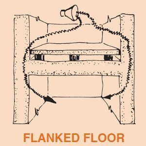
The word “flanking” is used to describe a vibration or noise path that goes around an isolated component. If a structure is built with continuous walls so that in cross section it is as an H and we introduce a floating floor, the STC of the system will probably remain at only 60 or 63 regardless of the floor’s rating. Sound energy vibrates the walls and this vibration continues in wave form to the lower spaces where the wall reintroduces the sound. This is flanking or bypassing the floating floor. The difference in results is shown in Test Two as opposed to Test One in the beginning of our discussion on page 3. The floor constructions were exactly the same. In Test One, however, the sound impinged directly on the walls and ceiling without the isolated barrier walls and ceiling used in Test Two.
To complete an envelope, secondary walls must be introduced with the same consideration given to mass and air gap as covered in the floor discussion. The problem is simpler, because the walls normally support only their own weight and they need not have the structural strength of the floor. Poured concrete or concrete block walls should approach the floor density. It is most important that block joints are properly filled with mortar and painting the walls so the construction is more nearly airtight helps.
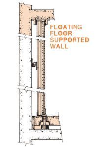
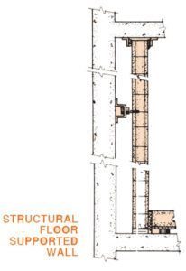
The best approach is resting these walls on the perimeter of the floating floor so the floor isolation system serves the walls as well. If this is not possible, the second choice is supporting the isolated wall on the structural slab with continuous LDS pads, and providing a caulked fiberglas seal between the floating floor and the wall as described for the perimeter in the previous specifications.
If the wall is so high as to be unstable it must be protected against buckling or toppling by means of resilient sway braces anchored to the structural walls. Sway braces are mandatory for all independent walls resting on pads if they are not locked at the top. Braces are normally placed 4’ apart horizontally with the vertical spacing of rows dependent on the height and thickness of the wall. It is seldom that more than two rows of braces are required.
Occasionally we have used double acting springs for sway braces in conjunction with spring mounted floors. In most cases, however, our recommended design is the LDS Type DNSB as illustrated on page 20. When space is limited, the WIC clip is the logical alternate.
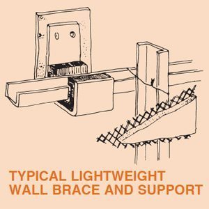
Yet another variation, Type WCL, consists of a channel shaped bracket that is lined with 5/16” LDS waffle pad and a 1/4” thick felt backing. With this arrangement the bracket is bolted to the structural wall so that horizontal steel furring can be laid in the isolated pocket as illustrated.
When we did our test work at Riverbank, we did not place lightweight fiberglas fill between the walls of our inner room and the walls of the laboratory. Concrete short circuited the air gap and we had to break it out. Therefore, under Construction Procedure you will find that we have said that “special care must be taken to completely butter all joints and concrete must not be allowed to drop behind the wall and short circuit the air gap”.
If you wish to be more cautious about concrete droppings, you can call for 11/2” or 2” thick three pound minimum density fiberglas to fill this vertical void. Call for the fiberglas in the materials portion of the specification and then in the construction procedure advise the contractor to cement the fiberglas to the structural wall in advance of the placing of the concrete blocks. Thus, the fiberglas will serve to prevent accidental short circuiting of the air gap. It is primarily a mechanical rather than an acoustical aid.
We must also be concerned with sound leakage over the top of the wall. If a wall is short and rigid and need not be locked at the top, the least expensive approach is the inclusion of a fiberglas pad over the last course of masonry with acoustical caulking on both sides of the pad. In most cases, it is easier to both lock the walls in place and seal them by the use of continuous angle brackets type AB-716 which are placed on both sides of the wall.
If the walls are stable and it is possible to rest the floating ceiling on the floating walls to complete the box, there is no need for these top details.
When an isolated wall abuts the rigid structure, it is usual to place a fully caulked strip of fiberglas or 1/2” neoprene sponge at the end to prevent short circuiting. AB-716 angle braces can be used vertically as well for locking purposes or a caulked vertical section of channel iron lined with 1/2” neoprene sponge makes another neat joint as the wall fits between the flanges.
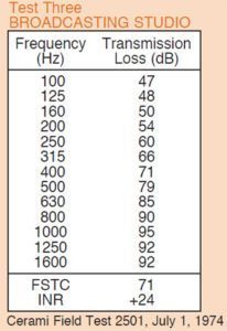
If some lesser STC values are satisfactory, it is not necessary to use masonry. Good results can be obtained with gypsum board walls or various of the prefabricated acoustical partitions as shown by Test Three of a small broadcasting studio using a 4” jack-up concrete floor, gypsum board walls on three sides and an isolated ceiling. You will note that rather than the 79 STC obtained with the 2” air gap in the Riverbank Test, this room came in at FSTC 71 with an INR of plus 24. These are excellent results and probably more than satisfactory for most situations. This less expensive construction should certainly be considered. The type WCL clip was used to resiliently support horizontal runners and we had included fiberglas behind the walls as always for lightweight construction.
Isolated walls are often used without floating floors to reduce sound transmission between adjacent spaces. Here the floor provides a possible flanking path, but if results in the STC 60 range are satisfactory this is certainly a valid technique. All of the wall specifications are meant to be used with or without the floor specifications as required.
