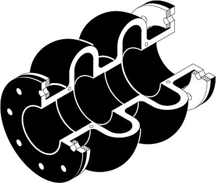
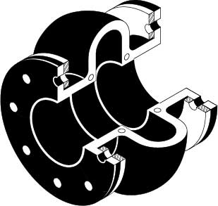
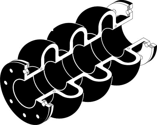
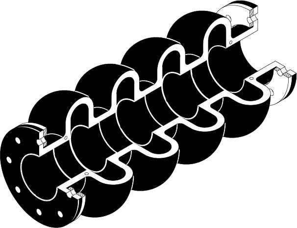
1002
Expansion joints installed in piping systems that are anchored on both sides of the joint.
No control rods are necessary. If control rods are installed as a safety measure, the locking nuts must be backed off with a clearance equal to the specified axial movement. The expansion joint will exert a thrust force on the anchors. To calculate pressure thrust on anchors use the following equation:
Pressure Thrust = (Pressure Thrust Area) x (Rated Working Pressure)
Expansion joints installed in unanchored piping or connected to isolated equipment.
Control rods are necessary. Once control rods are installed the joint will no longer act as an expansion joint, since the pressure will extend the joint to the nuts of the control rods. The joint will no longer take up axial motion. It will make up for misalignment, transverse and possibly angular motion. The nuts of the control rods should be threaded against control rod gussets, thereby preventing joint from extending.
Expansion joint flanges must be in contact with a flat faced or 1/16″ standard raised face flange. Depressions or protrusions typical of vitaulic or similar type flanges must be covered with a steel spacer flange first. Rubber flanges will not retain loose elements in valve bodies that rely on contact with a steel flange. A steel spacer flange must be inserted between the rubber expansion joint and the valve body
| Series 1000 |
Tube | Cover | Max Oper. Temp. |
| B | Butyl | Butyl | 250°F |
| E | EPDM | EPDM | 250°F |
| H | Hypalon | Hypalon | 225°F |
| HN | Hypalon | Neoprene | 225°F |
| N | Neoprene | Neoprene | 225°F |
| NH | Neoprene | Hypalon | 225°F |
| Ni | Nitrile | Nitrile | 210°F |
| NiN | Nitrile | Neoprene | 210°F |
| NR | Neoprene | Natural | 225°F |
| R | Natural | Natural | 180°F |
| RN | Natural | Neoprene | 180°F |
| V | Viton® | Viton® | 250°F |


