PRODUCT DETAILS
There are two types of resiliently suspended ceilings.
The most common is a lightweight mechanical ceiling that contains the lighting fixtures, the outlets for the air conditioning system, etc. These lightweight ceilings consist of light steel framing drop-in absorptive tiles that are generally 24”x24” or 24”x36”. The primary purpose is to absorb sound within the room and to lower the reverberation rate. Because the material is so light, there is virtually no reduction in transmitted noise either in or out of the room.
Acoustical barrier ceilings are entirely different. In years past they might have been plaster on wire lathe, but modern construction is two layers of 5/8” gypsum board screwed together with staggered joints. Every effort is made to seal the perimeter as well as any penetrations. While these ceilings are still lightweight as compared to concrete floating floors, they do have sufficient mass to act as sound barriers and the fact that they are carefully caulked and sealed puts them in a totally different category than the mechanical ceilings described above.
Barrier ceilings are primarily used to reduce noise transmission from the floor above. In most cases an architect will choose either a floating floor in the equipment room or a barrier ceiling in the space below. However, the two methods are sometimes used in conjunction with one another.
In other applications the ceilings help contain noise. Thus, an equipment room may have a suspended ceiling to complete the isolated wall and floor design. This is a common procedure for adjacent music practice rooms, particularly when the double partition walls do not reach all the way to the structural ceiling.
Barrier ceilings are light as compared to floating concrete floors, so the effectiveness of the ceiling is far more dependent on the air gap than mass or rigidity. Since the air must allow for the inclusion of the hangers and support steel, a minimum air gap is about 12”. Lightweight fiberglas bats are placed over the barrier ceiling to further improve the performance.
The building service ducts, electrical conduits, etc., pass beneath it and above a removable tile mechanical acoustical ceiling. The acoustical hangers are located in the supporting rods or wires common to both ceilings. When the barrier ceiling is penetrated by wires, rods or straps, these members must be isolated by means of resilient sleeves and they should be caulked as well.
While the double ceiling method is probably the most effective approach to the problem, vibration hangers are commonly used to support single ceiling systems as well. If the single ceiling is of the sound barrier type, the vibration isolator helps to prevent the passage of structural noise just as in the case of the double ceiling. Hangers used to support simple mechanical ceilings prevent rattling of the ceiling members.
A mounting that “looks into” or rests on a rigid structure has a simpler task than one working against something that is flimsy. In the case of floating floors, the LDS isolators or springs rest on the main structure, which is comparatively rigid. In the case of ceiling hangers, we often start with the noise and vibration at the concrete building structure and move down a rod or wire to the vibration control hanger and then on to the suspended ceiling. Under the best of circumstances, when this is a plastered ceiling, it is still a very flexible diaphragm without concentrated mass as compared to the concrete floor that a floor mounting rests on. Therefore, a hanger must be very carefully designed or it will not have the comparative flexibility to do the job.
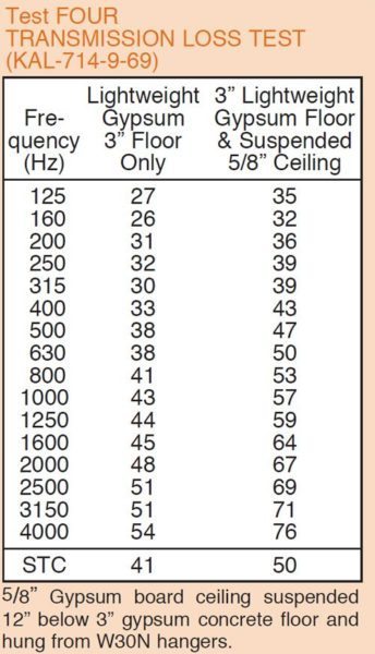
Very little test work has been done to show the effectiveness of acoustical ceilings using isolation hangers. In 1969 we tested lightweight components. We started with a 3” gypsum concrete floor with an STC of 41 and suspended a single 5/8” gypsum board ceiling using W30N hangers with 1” static deflection. The air gap was 12” . The STC went up to STC 50 for an improvement of nine as tabulated in Test Four. Most ceilings are made up of two layers of 5/8” gypsum board with lightweight fiberglas bats laid over the top. Therefore, it is safe to assume that the average barrier ceiling provides an improvement of STC 14.
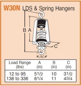
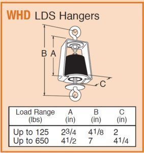
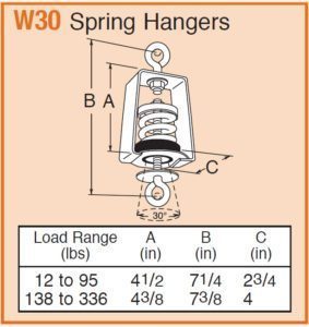
We manufacture a very wide range of ceiling hangers in order to be competitive when other vendors are specified. In this bulletin, however, we are discussing only three major categories consisting of the WHD, W30 and W30N. Our suggestions are as follows:
Series WHD – Simple LDS vibration hangers are used in low budget applications or for those installations where it has been clearly established that there is little or no structural vibration. The hangers serve as noise breaks only, as static deflection is limited.
Series W30 – Steel coil spring vibration hangers are far superior to the LDS designs because the higher deflection spring element will serve to isolate building vibration. The design includes a LDS cup in series with the spring that acts as a partial high frequency noise barrier.
Series W30N – Combination hangers make use of the WHD LDS element in series with the W30 spring. Thus the design combines the best features of the all LDS and the spring hangers and we recommend them for all critical applications.
15° Misalignment Tolerance – Both our spring and combination spring and LDS hangers are designed so that the hanger rod or wire can be off vertical by as much as 15° without rubbing on the steel hanger box and transmitting noise. We continue to manufacture lower priced competitive hangers that do not have this angular tolerance, but we invented the 30° sweep design, because most field problems stem from a contractor’s difficulty in lining up what may be hundreds of hangers perfectly. If they do not, the wires and rods rub.
Precompression – We strongly recommend that all spring hanger installations have the spring elements partially precompressed at the factory before they are installed. If the springs are not precompressed, the ceiling will descend as much as an 1” when the spring deflects as weight is added. The contractor will have great difficulty in preventing cracks in plaster ceilings or finishing with a flat ceiling at the proper elevation. When the spring hangers are precompressed 70% of the total travel, the ceiling will not descend at all until the installation is about completed and the travel will only be 0.30” to completion.
The architectural drawings should show the construction of the isolated ceilings and the spacing of the ceiling hangers. They are usually on 48” centers in both directions. The hanger most commonly used on our jobs and our standard recommendation is the Type W30N. Under Materials and Manufacturer, however, we have repeated the specification for each type so you can select your preference. Since the construction procedure is the same in all cases, it was pointless to keep rewriting the same specification over again. By the same token, the specification can be changed slightly to cover any type of construction such as a sand plaster ceiling or a simple acoustical tile ceiling by substituting your materials where we call for two layers of 5/8” Gypsum Board.
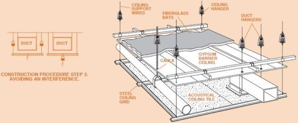
ISOLATED CEILINGS SUSPENDED BY RESILIENT HANGERS
- Scope
To prevent the transmission of noise and vibration through the ceiling hangers and the suspended ceiling. - Materials
- Combination LDS Element and Spring Hangers: Hangers shall consist of a steel frame containing an LDS isolation element at the top and a coil steel spring seated in an LDS cup on the bottom. Both the element and the cup shall be molded with an LDS bushing that passes through the steel frame. The LDS element shall be capable of a minimum deflection of 0.23”(6mm) and the steel springs selected from a 1”(25mm) static deflection series with a minimum additional travel to solid of 1/2”(12mm). Spring diameters and hanger box lower hole size shall be large enough to permit the hanger rod to swing through a 30° arc before contacting the box and short circuiting the spring. Hangers shall be selected for a minimum of 0.75”(20mm) spring deflection and factory precompressed 70% of the total deflection determined by the assigned load per hanger. Hangers shall be manufactured with provision for bolting or attaching to the ceiling flat iron straps, wire, rods or steel runners. Hangers shall be fail safe.
- Spring Hangers: Hangers shall consist of a steel frame containing a coil spring seated in an LDS cup. The cup is molded with a rod isolation bushing that passes through the hanger frame. Hangers shall be selected from a 1”(25mm) static deflection series with a minimum additional travel to solid of 1/2”(12mm). Spring diameters and hanger box lower hole size shall be large enough to permit the hanger rod to swing through a 30° arc before contacting the box and short circuiting the spring. Hangers shall be selected for a minimum 0.75”(20mm) spring deflection and factory precompressed 70% of the total deflection determined by the assigned load per hanger. Hangers shall be manufactured with provision for bolting or attaching to the ceiling flat iron straps, wires, rods or steel runners. Hangers shall be fail safe.
- LDS Hangers: Hangers shall consist of a steel frame containing an LDS isolation element molded with a rod isolation bushing that passes through the hanger frame. Deflections shall be a minimum of 0.23”(6mm) and a maximum of 15% of the elements height. The dynamic frequency shall not exceed 10Hz. The isolation elements shall be molded to the following AASHTO Table 1 bridge bearing properties. Hangers shall be manufactured with provision for bolting or attaching to the ceiling flat iron straps, wires, rods or steel runners. Hangers shall be fail safe.
AASHTO Bridge Bearing Specifications for Polyisoprene ORIGINAL PHYSICAL PROPERTIES TESTED FOR AGING COMPRESSION SET ASTM D-395 22hrs/158°F Method B LONG TERM CREEP ISO8013 168 hrs Tests: Tests: ASTM D-2240 & D-412 OVEN AGING(70hrs/158°F)
ASTM D-573OZONE
ASTM D-1149ASTM D-395 ISO8013 Durometer Shore A Tensile Strength (min) Elongat. at Break (min) Hardness (max) Tensile Strength (max) Elongat. at Break (max) 25 pphm in air by Vol. 20% Strain 100°F 22hrs/158°F Method B 168 hrs 40±5 2000 psi 500% +10% -25% -25% No Cracks 25%(max) 5%(max) 50±5 2250 psi 450% +10% -25% -25% No Cracks 25%(max) 5%(max) 60±5 2250 psi 400% +10% -25% -25% No Cracks 25%(max) 5%(max) 70±5 2250 psi 300% +10% -25% -25% No Cracks 25%(max) 5%(max) NOTE: 40 Durometer is not included in AASHTO Specifications. Numbers are Mason standar
- Closed cell neoprene sponge 1/4”(6mm) thick.
- One and a half to three pound density 2”(50mm) thick fiberglas.
- Isolated Ceiling Construction Procedure.
- Lay out ceiling support wires on 48”(1220mm) centers in both directions.
- Where ducts or other mechanical interferences occur, a rigid steel trapeze can be run under the interference and a ceiling hanger hung from the trapeze to maintain the 48”(1220mm) centers. Where head room does not allow for this, the steel trapeze can be installed with an isolation hanger on each end and a ceiling wire hung from the trapeze to the floating ceiling.
- Install isolation hangers making certain that hangers are vertical and that they do not rub against pipe, duct, ceiling beams or other interferences.
- Connect wires to lower end of hangers and proceed with steel ceiling grid construction in the normal manner. Attach the first layer of 5/8”(16mm) gypsum board to the ceiling steel covering the upper surface of the gypsum board with 2”(50mm) fiberglas bats as completely as possible.
- Attach the second layer of 5/8”(16mm) gypsum board being certain to stagger the joints in all cases.
- Install lightweight angles around the perimeter of the ceiling by bolting one leg to the wall and resting the 1/4”(6mm) neoprene sponge on top of the horizontal leg so as to provide a support for the perimeter.
- Caulk the perimeter.
- When an acoustical tile ceiling is to be used below the sound barrier ceiling, continue the hanger wires to the acoustical ceiling and caulk all hanger wire penetrations where they pass through the gypsum ceiling.
- Where mechanical equipment, pipes or ducts fall below the barrier ceiling, provide additional hangers that are not connected to the barrier ceiling for this equipment and sponge sleeves where these rods pass through the barrier ceiling. Caulk the perimeter of all sleeves.
- Continue with the construction of the acoustical tile ceiling in the normal manner.
- Submittals
- Load/deflection curves of all hangers. Certification of the LDS compound to the AASHTO specifications as well as the Dynamic Frequency.
(Use 2 for W30N or W30 only) - A full scale drawing of the hangers showing the minimum 30° contact arc in all planes. Submittals shall include compressed spring height and spring rates.
- Load/deflection curves of all hangers. Certification of the LDS compound to the AASHTO specifications as well as the Dynamic Frequency.
- Manufacturer
- Subject to compliance with the specifications, the following products are approved for use: (Select One) (Type W30N Combination Spring and LDS Hangers.) (Type W30 Spring Hangers.) (Type WHD Double Deflection LDS Hangers) as manufactured by Mason Industries, Inc.
