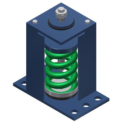
SSLFH – 2″ DEF.
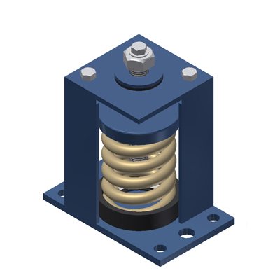
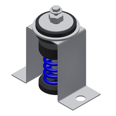
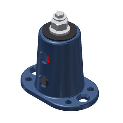
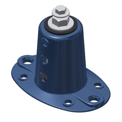
Equipment shall be installed on resilient mountings designed and rated to resist seismic forces in all directions. The snubber shall be adjustable in the vertical up direction and allow a maximum of 1/4” (6mm) travel in the vertical and horizontal direction before contacting the resilient snubbing collars. Mountings shall have an Anchorage Preapproval “OPA” Number from OSHPD in the state of California attesting to the minimum listed certified Horizontal and Vertical load ratings. All mountings shall have adjusting bolts that are rigidly bolted to the equipment. Spring diameters shall be no less than 0.8 of the compressed height of the spring at rated load. Springs shall have a minimum additional travel to solid equal to 50% of the rated deflection. Mountings shall have a minimum of 2 spring inspection ports. Submittals shall include spring diameters, deflections, and calculations signed by a registered engineer showing that the seismic loads the mountings are to resist have been properly calculated. Mountings shall be type SSLFH as manufactured by Mason Industries, Inc.
| SIZE | RATED CAPACITY (lbs) | RATED DEFLATION (in) | MOUNT CONSTANT (lbs/in) |
| 101 | 125 Ibs | 2.50 in | 50 |
| 102 | 200 Ibs | 2.50 in | 80 |
| 103 | 310 Ibs | 2.50 in | 125 |
| 104 | 500 Ibs | 2.50 in | 200 |
| 105 | 740 Ibs | 2.40 in | 310 |
| 106 | 1050 Ibs | 2.10 in | 500 |
| 107 | 1400 Ibs | 2.00 in | 700 |
| 108 | 1660 Ibs | 2.05 in | 810 |
| 109 | 2250 Ibs | 2.00 in | 1125 |
| 110 | 3000 Ibs | 2.00 in | 1500 |
| 111 | 4000 Ibs | 2.00 in | 2000 |

