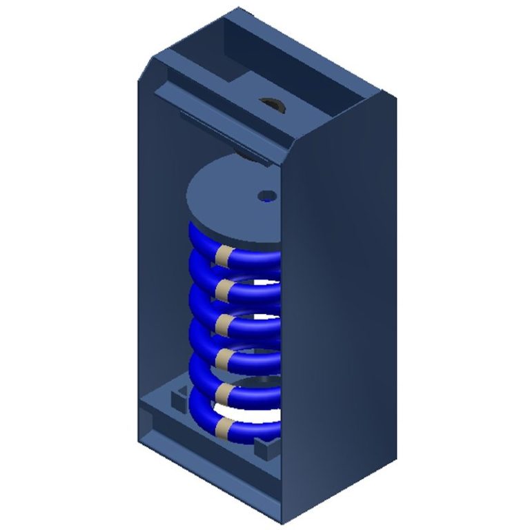
30N – 3” DEF. 1000 SERIES
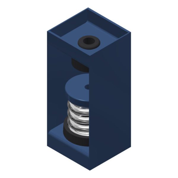
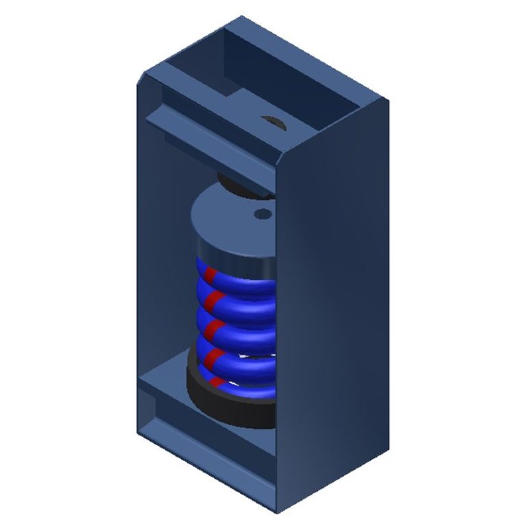
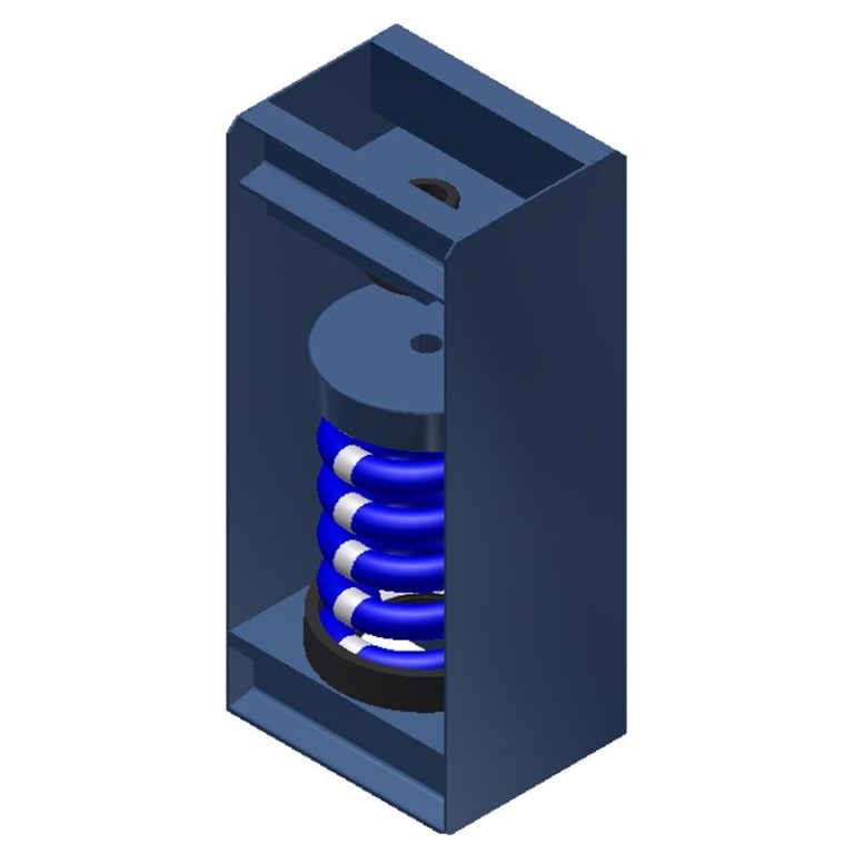
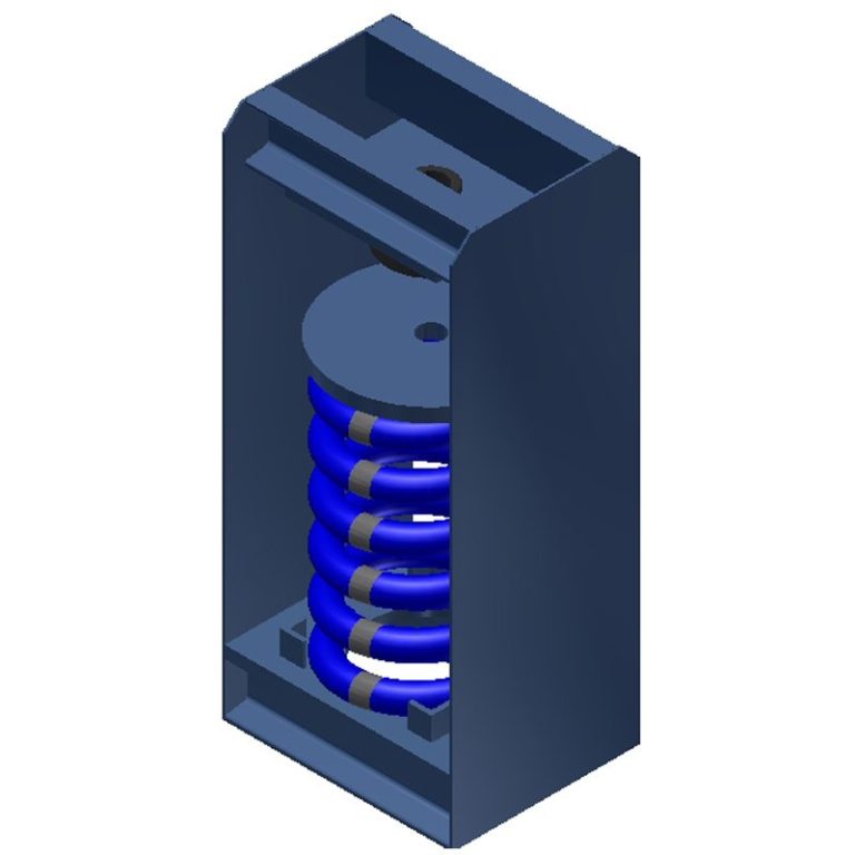
Hangers shall consist of rigid steel frame containing a minimum 1-1/4” (32mm) thick LDS rubber element at the top and a steel spring with general characteristics as in specification B seated in a steel washer reinforced LDS rubber cup on the bottom. The LDS rubber element and the cup shall have molded bushings projecting through the steel box. In order to maintain stability the boxes shall not be articulated as clevis hangers nor the LDS rubber element stacked on top of the spring. Spring and hanger lower hole diameters shall be large enough to permit the hanger rod to swing through a 30° arc from side to side before contacting the cup bushing and short circuiting the spring. Submittals shall include a hanger drawing showing the 30° capability. Hangers shall be type 30N as manufactured by Mason Industries, Inc.
| SIZE | Rated Capacity (Ibs) | Rated Defl (in) | Spring Constant (Ibs/in) | MRD (in) |
| 1082 | 15 | 3.00 | 5 | 3/8 |
| 1083 | 24 | 3.00 | 8 | |
| 1084 | 33 | 3.00 | 11 | |
| 1085 | 48 | 3.00 | 16 | |
| 1086 | 60 | 3.00 | 20 | |
| 1087 | 75 | 3.00 | 25 | |
| 1088 | 111 | 3.00 | 37 | |
| 1089 | 150 | 3.00 | 50 | |
| 1090 | 195 | 3.00 | 65 | |
| 1091 | 270 | 3.00 | 90 |

