It is often necessary to provide a wooden floating floor rather than the heavier concrete construction with wood topping. Cost or weight restrictions may be the factor. In older buildings it is often necessary to improve on existing floors with a lightweight impact noise resistant construction. A resiliently supported wooden floor will reduce the rumbling noise of a bowling ball, the click, click of a woman’s heels and that portion of a typical noise generated by a piano that travels down the piano legs and into the structure. It will offer only minor reduction of airborne sound, as there is insufficient mass in the surface. In some applications on stages or in rehearsal rooms the primary purpose is relief and comfort for the dancers. Landing on concrete or hard mounted wood surfaces is very damaging to a dancer’s feet and legs.
We have run some tests on INR and IIC as noted below, and hope to run other tests on STC, but have not done so at this writing. We have seen meaningful results, however, using this construction under judo rings, rehearsal dance floors, bowling alleys, gymnasium floors and high school machine shops.
In most cases, we have used our type ND mountings, and occasionally our type MFS spring designs. We have included a typical specification using the ND mountings and prefer not to write a general specification for springs, as spring selections are very construction dependent. Please let us help you specifically on direct mounted spring applications.
Our wooden floor specifications can be modified depending on your specific construction and finish. For example, rather than plywood you might be using heavy tongue and groove sub-flooring across the sleepers and a hardwood finish.


WOODEN FLOATING FLOORS FOR DANCE FLOORS, STAGE FLOORS, BOWLING ALLEYS, GYMNASIUMS, LIGHT DUTY MACHINE SHOPS, ETC.
- Scope
Isolate the wooden floating floor from the building structure by means of double deflection LDS isolators and perimeter isolation. - Materials
- Sleepers: Kiln dried 2×4’s minimum 12’(3.6m) long.
- Flooring: 2 layers 3/4”(20mm) AC plywood.
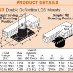
- LDS Isolators: Minimum of 11/2”(40mm) high with an extended LDS covered base plate and a tapped steel insert on top. Isolators shall be selected for a maximum of 0.23” deflection and shall be molded to the following AASHTO Table 1 Bridge bearing properties.
ORIGINAL PHYSICAL PROPERTIES TESTED FOR AGING COMPRESSION SET ASTM D-395 22hrs/158°F Method B LONG TERM CREEP ISO8013 168 hrs Tests: Tests: ASTM D-2240 & D-412 OVEN AGING(70hrs/158°F)
ASTM D-573OZONE
ASTM D-1149ASTM D-395 ISO8013 Durometer Shore A Tensile Strength (min) Elongat. at Break (min) Hardness (max) Tensile Strength (max) Elongat. at Break (max) 25 pphm in air by Vol. 20% Strain 100°F 22hrs/158°F Method B 168 hrs 40±5 2000 psi 500% +10% -25% -25% No Cracks 25%(max) 5%(max) 50±5 2250 psi 450% +10% -25% -25% No Cracks 25%(max) 5%(max) 60±5 2250 psi 400% +10% -25% -25% No Cracks 25%(max) 5%(max) 70±5 2250 psi 300% +10% -25% -25% No Cracks 25%(max) 5%(max) NOTE: 40 Durometer is not included in AASHTO Specifications. Numbers are Mason standar
- Perimeter Isolation Sponge: Neoprene sponge 1/2”(12mm) thick.
- Fiberglass Insulation: Unfaced lightweight 11/2”(40mm) – 3# Density Fiber-glass Insulation Batts
- Floor System Construction Procedure
- Cement 1/2”(12mm) thick neoprene sponge to walls around entire floor area. Neoprene strip should be full height of overall construction.
- Counter bore holes on 24”(600mm) centers in underside of 2×4 sleepers so that the depth allows for an unloaded clearance of 5/8”(16mm) between the underside of the sleeper and the top of the isolator base plate. Holes shall be large enough to provide a minimum clearance of 1/4”(6mm) all around the diameter of the isolators. Bolt the isolators to the 2×4 with flat head machine screws in countersunk holes.
2a. When height is not critical, use the following alternate.
Invert the LDS isolator and nail securely to the underside of the 2×4 sleeper on the center line. - Place the sleepers all around the perimeter of the room up against the neoprene sponge perimeter isolation.
- Place the balance of the sleepers in parallel rows on 16”(405mm) centers across the room as shown on the drawings.
- Lay 11/2”(40mm) – 3# Density Fiberglass Insulation between rows of sleepers.
- Attach the first 3/4”(20mm) layer of plywood to the sleepers with 2” (50mm) flat head screws on 16”(405mm) centers. Lay the rows of plywood down so the joints are staggered by 48”(1220mm) and the plywood is snug against the perimeter neoprene sponge.
- Lay the second layer of 3/4”(20mm) plywood down with the joints offset 16”(405mm) in both directions in relation to the first layer. Attach the second layer of plywood to the first by means of 11/2”(40mm) long flat head wood screws on 16”(405mm) centers in both directions. Use wood glue between layers.
- Apply floor finish as shown on the drawings.
- Submittals
- Load and deflection curves of all isolators.
- Certification of the elastomeric compound to the listed AASHTO specifications.
- Manufacturer
- The following products are approved for use: Double Deflection LDS Mountings manufactured to AASHTO specifications.
Mountings shall be Mason Industries, Inc. Type ND-BBP.
- The following products are approved for use: Double Deflection LDS Mountings manufactured to AASHTO specifications.
