Mountings - SLR Spring Mountings
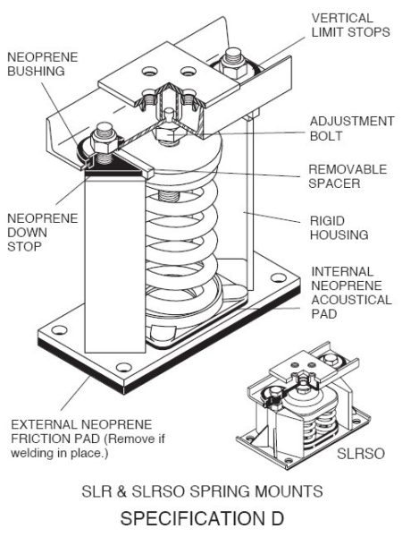
SLR and SLRSO restrained mountings limit upward travel when weight is temporarily removed and provide safety stops for windy rooftop applications. All mountings are shipped with removable steel spacers between the sides and the top plate of the mounting as shown in the illustration. When the spacer is in place, the mountings are rigid blocks that support the equipment at elevation before spring adjustment. After the springs are adjusted to take the load, the spacers are removed to provide the operating clearance without changing the height of the mounting. The stop nut is adjusted to provide a clearance of 0.125”(3mm) to complete the adjustment. When there is a radical weight change, such as the water and refrigerant being removed from a chiller, the water drained from a steam generator or a cooling tower, the upward spring expansion is limited by the clearance under the stop nut.
In extremely windy situations, overturning is limited to this same movement plus the downward movement of the mountings on the opposite side. In most countries, other than those experiencing storms with higher velocities, designs are based on 100 miles per hour winds which exert a pressure of 30 lbs. per square foot on the equipment. The force can be calculated using the largest vertical surface to check whether the housing rating of the mountings is adequate, both horizontally and vertically.
The call out of minimum clearance around the restraining bolts is very important, since it offers some assurance that the springs will
not be short circuited when there is minor misalignment of the housings because of structural tolerances in the steel work or attachments. SLR’s and SLRSO’s are used under chillers and steam generators as well as roof top equipment such as cooling towers, heating and ventilating units and blowers. They are often used as pipe horizontal supports as well, because the upper steel surface facilitates stanchion attachment.
SPECIFICATION D
Equipment with large variations in the operating and installed weight, such as chillers, boilers, etc., and equipment exposed to the wind such as cooling towers, roof mounted fans and roof mounted air handling equipment shall be mounted on spring mountings, as described in Engineering Specification B, including the neoprene acoustical pad within a rigid housing that includes vertical limit stops to prevent spring extension when weight is removed and temporary steel spacers between the upper and lower housings. Housings shall serve as blocking during erection. When the equipment is at full operating weight, the springs shall be adjusted to assume the weight and the spacers removed, without changing the installed and operating heights. All restraining bolts shall have large rubber grommets to provide cushioning in the vertical as well as horizontal modes. The hole through the bushing shall be a minimum of 0.75” (19mm) larger in diameter than the restraining bolt. Horizontal clearance on the sides between the spring assembly and the housing shall be a minimum of 0.5”(13mm) to avoid bumping and interfering with the spring action. Vertical limit stops shall be out of contact during normal operation. Cooling tower mounts are to be located between the supporting steel and the roof or the grillage and dunnage as shown on the drawings when there is no provision for direct mounting. Housings and springs shall be powder coated and hardware electro-galvanized. Mountings shall be SLR or SLRSO as manufactured by Mason Industries, Inc.
