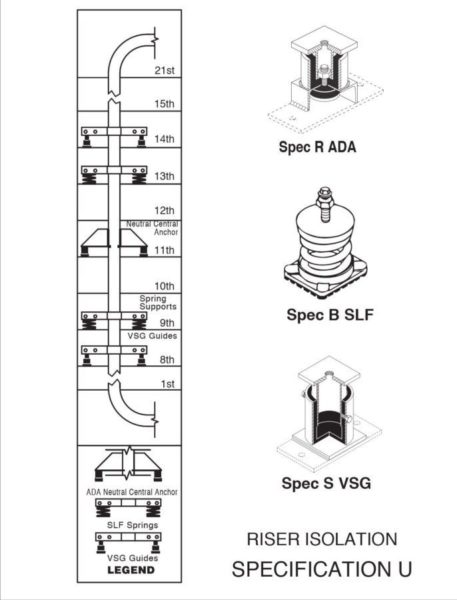
RISER ISOLATION
thermal expansion or contraction is a minor issue. It is often possible to solve the problem by providing a single basement support and guides at the midpoint and roofline. If thermal motion is larger, an isolator in the center of the structure will allow for half motions in both directions. The application is completed with a few resilient guides.
In high rise work the situation is entirely different. We often work with massive risers where a single 20 story length is common. Single risers that run 40 stories or more are not that unusual. The thermal effects become very important and the risers become so heavy that it is necessary to distribute the weight on a number of floors. When the isolation is not critical, there is still the structural problem. Once an anchor is established, the supports must be able to follow the motion. As the pipe expands, it will lift off simple devices, such as pads and shift the load to the lowest or lower stories. Should the pipe contract, it will lift off pads in the lower sections and transfer the load to the top. Not allowing or considering this phenomena, has resulted in structural failure of the riser supports.
A riser may be resiliently supported in the basement or on a column that is bolted to a basement pier. Assuming branch off connections are not a problem, and the horizontal run at the roof has allowed for expansion, when the system expands, there is no structural problem as none of the load rested on the intermediate floors to begin with. The same is true if the system contracts.
In another example the pipe rises through a building where pipe clamps or brackets are used to transfer the load to successive floors. These attachments may or may not rest on isolation pads. When the system was installed at ambient temperature, all of the floors assumed part of the load. When the system is filled with water, there might be minor deflection in some of the floors to adjust to the slightly shorter or longer length, but this higher load is still evenly distributed.
However, if this is a hot water system with 2”(50mm) expansion, the top clamp would rise 2”(50mm) above structure. At the mid point 1”(25mm), at the quarter point 0.5”(13mm), etc. If there are no pads, the total load shifts to the lower 1 or 2 clamps immediately. If there are pads, the load shifts completely as soon as it exceeds the small initial deflection of the upper pads and this leads to the structural problem.
We are suggesting a safer system. Starting with the same parameters, it is always better to cut the motion at the two ends in half by establishing a neutral central resilient anchor. This anchor assumes no load. It is only there to direct the movement in the two directions.
Regardless of the length of the riser, there are an equal number of supports points, both above and below the anchor. An extreme design would be a support on every floor, but commonly they are on every third floor. These supports are selected with a minimum deflection of 0.75”(19mm), but four times the pipe travel at any given location. Since the ends are moving 1”(25mm) up at the top and 1”(25mm) down at the bottom, these mountings would have 4”(100mm) static deflection. Half way to the anchor, both top and bottom, the movement would be 0.5”(13mm) and the isolator deflection 2”(50mm). In this example these four mountings would have enough capacity for the entire riser weight. That is why the neutral central anchor is not statically loaded.
When the expansion takes place, the top hanger would lose 25% of the 4”(100mm) deflection or 25% of its load and the mounting midway to the top would experience the same proportionate phenomena. The two mountings below the anchor point would be compressed an additional 25% each, so there is a load shift of minus 25% above and plus 25% below the anchor. Therefore the anchor location remains neutral. This load change of plus or minus 25% per support location is minor and causes no difficulty.
For a complete discussion, please refer to our Bulletin Riser-112 in the “Hangers, Piping Anchors, etc.” section of the catalog. The specification reflects this system.
SPECIFICATION U
All vertical risers shall be supported by spring isolators designed to support the riser filled with water, if it is a water line. Assigned loads must be within the building design limits at the support points. Neutral central resilient anchors close to the center of the run shall direct movement up and down. The anchors shall be capable of holding an upward force equal to the water weight when the system is drained. If one level cannot accommodate this force, anchors can be located on 2 or 3 adjacent floors. Resilient guides shall be spaced and sized properly depending on the pipe diameter. Submittals must include the initial load, initial deflection, change in deflection, final load and change in load at all spring and anchor support locations, as well as guide spacing. The initial spring deflection shall be a minimum of 0.75”(19mm) or four times the thermal movement at the isolator location, whichever is greater. Calculations shall include pipe stress at end conditions and branch off locations and the manufacturer must include installation instructions. Submittal must be stamped and signed by a licensed professional engineer in the employ of the vibration vendor for at least 5 years. Proper provision shall be made for seismic protection in seismic zones. The isolator manufacturer shall be the same firm supplying the mechanical contract. Support spring mountings shall be Specification B, anchors Speci-fication R, telescoping guides Specification S.
OPTIONAL ADDITION TO SPECIFICATION
The isolation vendor shall design and provide all brackets or clamps at riser spring guide and anchor locations. The contractor must install and adjust all isolators under the supervision of the isolator vendor or his representative.
